In this article I will model a lock on a river or canal. As well as going into the specifics of the model, I’ll touch on more general topics about modelling. These are things like diagrams to represent the model, tools, models as conversation starters, iterating models etc.
A lock has a model that is a nice level of size and complexity, which is why I’ve chosen it as an example of more general things about models. Also, I like rivers, canals and locks.
What is the real-world thing we’re thinking about?
A lock can make it easier for a boat or ship to navigate a river or canal. The problem they solve is the fact that river beds are rarely level – rivers flow downhill to the sea – but level rivers are easier for boats. A lock allows the river to be turned into a series of relatively level stretches of river joined by locks that absorb most of the difference in height (like a lift or elevator).

A lock has two sets of doors called gates – when these shut they block the river so no water can flow. (Actually, there’s usually an extra bit of river going around the side of the lock over a weir, but the lock gates completely shut the bit of river that contains the lock, and most boats wouldn’t want to go over the weir.) The gates on the upstream / uphill end of the lock are usually called the top gates, and those on the downstream / downhill end are the bottom gates.
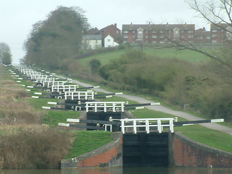
The gates can be single – coming from only one side of the lock – or double (one coming from each side of the lock, to meet each other in the middle of the river). In the photo above, the bottom gates are double and the top gate is single. The gates open against the flow of the river, i.e. the river will tend to close them. This means that a gate can normally be opened only if the river level upstream from them is the same as that downstream from them (this will become important later).
Gates have a little door in them called a paddle, which can be raised or lowered. When a paddle is raised, water can flow downstream through it (but this is less than would flow through an open gate). If you look in the photo, on top of the bottom gates are a couple of metal structures. These are the mechanisms for raising and lowering the paddles – the right paddle is raised, as indicated by the black metal thing sticking up near the life buoy. Sometimes the paddles are set into the walls of the lock, rather than onto the gates, but they always have the same purpose.
The purpose of the gates is two-fold:
- Allow a boat to enter and leave the lock
- Hold back all / most of the water upstream from them while the lock empties or fills.
The purpose of the paddles is to allow water to enter or leave the lock gradually so that it can empty or fill.
Note that the lock never completely empties, otherwise a boat in it would run aground and so couldn’t enter or leave the lock. It’s as if it’s a lift going between two floors in a building – the lock full (matching the water level upstream from the lock) is the higher floor, and the lock “empty” (matching the downstream water level) is the lower floor.
There are some complications I’m deliberately leaving out for now – these will be covered later.
A finite state machine to describe a lock
There are four variables that you can control in a lock:
- Whether the top gates are open or shut
- Whether the bottom gates are open or shut
- Whether the top paddles are raised or down
- Whether the bottom paddles are raised or down
Together these control two other variables:
- The level of water in the lock.
- Whether the water level is static, rising or falling.
I’ve modelled a lock like this:
![Finite State Machine for a lock. A boat going upstream would pass from [bottom gates open, bottom paddles down, top gates shut, top paddles down, lock empty], to [bottom gates shut, bottom paddles down, top gates shut, top paddles down, lock empty] to [bottom gates shut, bottom paddles down, top gates shut, top paddles up, lock filling], to [bottom gates shut, bottom paddles down, top gates shut, top paddles up, lock full] to [bottom gates shut, bottom paddles down, top gates shut, top paddles down, lock full] to [bottom gates shut, bottom paddles down, top gates open, top paddles up, lock full]. A boat going downstream would go through a similar series of steps.](https://randomtechthoughts.blog/wp-content/uploads/2022/08/fsm-for-river-lock.png)
This is a finite state machine (FSM) – each blob is one state that the lock can be in, and the arrows show how the lock can move from one state to others. The two green states are ones where a boat can enter or leave the lock. The two purple states are ones that the lock will leave by itself, after enough time has passed. I could have modelled it in just text, or using some other kind of diagram e.g. a UML sequence diagram, but I felt that this kind of approach fitted it best.
Unlike other FSMs, there are no accepting or final states. You could use a FSM to e.g. check if some input is valid, in which case the FSM must be in one or more special end states by the time the input has run out. In the case of the lock, things can just go around forever.
If a boat wanted to use the lock to go downstream, it would:
- Start in the right-hand green state
- Go around the bottom of the middle part of the diagram
- End in the left-hand green state
If a boat wanted to use the lock to go upstream, it would:
- Start in the left-hand green state
- Go around the top of the middle part of the diagram
- End in the right-hand green state
This raises the first general question: What is the purpose of the model? What problem is it trying to solve? It probably can’t solve all problems, or at least can’t solve them well, so it’s worth concentrating on just the one problem it is trying to solve. Is it from the lock’s point of view, showing how it changes as it’s used by boats, or is it from the boat’s point of view? It might seem that doing it from the boat’s point of view would produce two models that were each smaller, but this is unfortunately not true.
If a boat went through the lock going upstream, the lock would end up in the right-hand green state. If the next boat to go through the lock were also going upstream, the lock would need to be emptied (as if a phantom boat were going downstream) before the lock could accept the second boat. Modelling from the boat’s point of view, assuming this would be a pair of models that each was a straight line of 6 states, would not cover this kind of case. I intended to model things from the lock’s point of view, which is why it is as it is.
You might have realised that there are several things missing, which is deliberate. The four variables I mentioned above that you can control are each binary, meaning that there are in theory 2 x 2 x 2 x 2 = 16 states. However, the diagram shows only half that number of states. For instance, if you are in the top right state of the central square of states, the only thing you can do is:
- Drop the top paddles
- Open the top gates
In real life you could just as well do these in the other order:
- Open the top gates
- Drop the top paddles
You would end up in the same green state to the right, but via a state that’s missing from the diagram. Whether this state and other missing states should be included is a matter of judgment, based on what the model is trying to achieve – are you trying to model all possible detail, or just a subset that supports an acceptable amount of behaviour?
An earlier version of the FSM
The diagram above is the second version of the model, produced using Visio. The first one is below, produced using GraphViz. The nice thing about GraphViz is that you can quickly type in a description of the blobs in the graph, and which blob is connected to which, and it will lay things out for you. The bad thing about GraphViz is that, even with the options it gives you, you can’t always lay things out in the way you’d like.

I deliberately included the earlier version of the diagram for a few reasons. They are essentially the same thing – the same set of blobs, connected in the same ways. However, the later version makes some things clearer, and I think this makes it do its job better.
I used GraphViz to quickly get stuff out of my head so I could look at it on the screen more easily. I had a break for a couple of hours, and my subconscious started to nag at me that the diagram was lacking some important things. Firstly, I realised that square of four states in the middle were the most important, and that there were symmetries between two pairs (an emptying pair and a filling pair).
Second, I realised that there were two states that were special because they would automatically change into other states after enough time (so they were coloured purple). Then I wanted to show how boats could enter or leave the dance, which is why I coloured two states green. Finally, I built on the symmetry of the central four states to show that the whole thing was symmetrical.
All of these bits of information were present in the earlier version, but it would be harder work to find them. The later version is more efficient in terms of the viewer’s time – important things present themselves more clearly.
The earlier version was not a waste of time – it fulfilled its purpose which was to get stuff out of my head onto paper, clearing enough space in my head for me to realise the important things I’ve just described. I had to change tool to move from one version to another, again for efficiency’s sake – I could get the appearance I wanted more quickly in Visio than I could in GraphViz.
In other circumstances I could have produced the earlier version on paper or a whiteboard. These likely would have been scrappy too, but that would also have been fine.
Why bother?
I hope that the diagrams are fairly easy to understand. They deliberately stay clear of code, and whether things would be implemented in one language or another, using object orientation, functional programming or something else. They provide a common ground for conversations to happen easily – for instance a tester or someone else with a critical eye could look at them, do the maths I described above and ask about the missing states. Maybe I missed them out in my thinking, as I was concentrating on only the happy path. Even on my own I can check them, and have a good idea of where I want to end up before I start.
Sometimes people throw the baby out with the bathwater in the name of agile. They so desperately want to avoid spending too long designing up front, that they don’t do enough designing. I find this a bit weird, if you consider what agile is meant to be about (rather than its trappings). For me, agile is a continuous and diligent focus on keeping the team effective and efficient. If a particular document or meeting isn’t worth doing – don’t do it. However, the corollary is also true – if a document (that’s not code) helps you and its costs are outweighed by its benefits, why not do it?
I spent 10 minutes doing the first version of the diagram, had a break for a few hours, then spent 10 minutes doing the second version. If I were turning the model into code, I would have avoided going down unproductive paths, and reduced the risk of leaving things out or creating bugs. Colleagues could also easily learn what I was up to, more quickly than if they had to read my code. Maybe they had a different idea as to the scope (see below) to me – and the model would bring that difference into the open quickly, while it is still relatively cheap and easy to do something about it. As I have seen several times before: days of coding can save minutes of designing.
Limits to the model’s scope
There are at least three things that could be in the model, but deliberately aren’t. What I’ve described is normal operation of the lock – boats go upstream or downstream, the lock gates open and shut, and the water inside the lock rises and falls. However, when the river’s in flood, often its rivers go into different mode that’s not covered by this model
Instead of trying to get rivers upstream and downstream, the objective is to get water downstream and out to sea as quickly as possible, so that the flood recedes. In this case, the top and bottom gates are opened at the same time (I’m not clear how this is achieved) so that the lock turns into a second weir (alongside the one that’s always there, next to it). No boats can travel on the river, which would be a bad idea anyway because hazards, such as bollards on the riverbanks, could easily be hidden by the floodwater.
I felt that this case was rare enough, and distinct enough from the normal cases, that I could leave it out of the models. However, in certain circumstances it might be worth including e.g. showing how both gates are opened at once.
The model above assumes the most common kind of lock, but there are at least two other kinds that it leaves out – the guillotine lock and the flight of locks. A guillotine lock looks like this:

The top gates have been replaced by a single large barrier that lifts up and down (like the blade of a guillotine). There are usually no top paddles; instead, you lift the guillotine up a little so that a small amount of water can pass underneath it. When you want to enter or leave the lock, the guillotine is lifted all the way out of the water. So, if you were to interpret “raise top paddle” as “lift top gate a little” then the model still works, but it needs this extra bit of interpretation.
A flight of locks is when the slope of the riverbed is too steep for a single lock. Instead, there is a series of two or more locks back-to-back. The top gates of one lock become the bottom gates of the next. You could model this by chaining together many copies of the model for a single lock, but with alteration so that adjacent models / locks share a gate.
In other circumstances, you could have nested models, to cope with a big model. For instance, you could have a FSM where one of its states is actually a nested FSM. Entering a state in the top-level FSM means you need to navigate the lower-level FSM from its start. Once you have got to the end of the lower-level FSM, you can then progress to the next state in the top-level FSM. This kind of thing allows you to zoom in and out of different levels of detail, so you don’t need to store all the complexity in your head (or on a single diagram) at once.
I deliberately left guillotine locks and flights of locks out of my model because that would have made them more complicated than I wanted, as I was aiming to just explain the general point of modelling locks.
Summary
In software it’s often tempting to rush in to coding, because that’s the thing that ships, that makes the tests pass etc. However, when you next feel this temptation, I encourage you to think about agility – is this the best way for me and the rest of the team to get to where we want to be? Would it be worth it to stop for a short while to think ahead? Then, what’s the best way to represent that thinking?
